
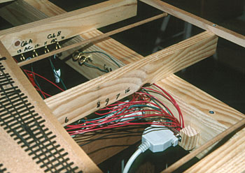
| Drawing on the experience of several preceding layouts, some standard techniques have been adopted for Minnipa. All connections between the main control panel and the layout, and between layout modules, are made using standard 25-pin or 9-pin computer cables and connectors. Within each module, all wiring is taken to brass eyelets screwed into the frame, and the final connections to the track are made with short droppers to the eyelets. The photo illustrates these features, which result in an arrangement which is easily constructed and simple to maintain. |
|
| Control is by conventional cab control, using my own controllers built to the Cooler Crawler design. These controllers give superb performance, are not difficult to construct, and can be built in several different walkaround configurations. DCC is a longer term possibility. | |
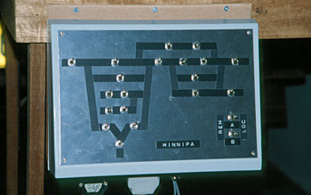
| Control panels are built as self-contained units using plastic angle-topped utility housings. All connections are via cables to connectors located along the bottom edge of the panels. The panel illustrated is for Minnipa, showing the mimic diagram and block selection switches. |
|