

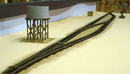
The layout was constructed with a mixture of 'Shinohara 12mm gauge' (code 70) and 'Peco HOm' (code 75) flexible track and points. These are two of the four brands of track available for HO scale 12mm gauge at the moment, the other two being Bemo and Tillig/Pilz. A comparison of the key features of the flextrack from each of these is tabulated below. All dimensions are scaled to prototype equivalent for comparison with the actual SAR specs.
After a number of years I found that the curved blade of the Peco HOm points tended to lose its curve, and being a casting it cannot be bent back into shape. This resulted in a pinching of the gauge on the curved road, leading to derailments. I have since replaced all the Peco points with Shinohara. I should point out that it is only the Peco HOm points which had this problem. I have recently been advised that Peco have changed the way they manufacture the blades of their HOm points, so all should now be well!
| Track | Sleeper length | Sleeper width | Sleeper height | Sleeper spacing |
| Prototype SAR | 6' 6" | 8" | 4-1/2" | 2' 8" |
| Shinohara | 7' 0" | 9" | 5" | 2' 3" |
| Peco | 7' 2" | 10" | 5" | 2' 2" |
| Bemo Code 70 | 6' 9" | 9" | 5" | 2' 0" |
| Tillig/Pilz | 6' 1" | 9" | 7" | 1' 11" |
The 2' 8" sleeper spacing shown for SAR prototype is that specified for "pioneer" lines. Later construction used spacings between 1' 9" and 2' 6".
|
|
Shinohara 12 mm gauge track at Yaninee, prior to ballasting. Compare this with the completed Yaninee scene here. |
| Over the years I have used what seems like every point control method (and every type of point motor) known to man. I eventually came to the conclusion that a simple form of direct manual operation was the most effective, as well as being very economical. | |
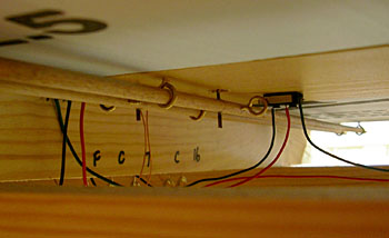
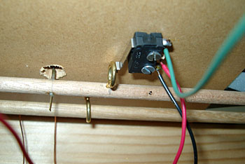
| For Minnipa, I devised a mechanism where the points are actuated by a simple length of dowel mounted in brass eyelet guides. A short length of brass tube is set into the dowel immediately below the points (crimped shut at the bottom), and a length of piano wire is simply dropped through the tiebar and down into the brass tube. When cut off just above the tiebar, it is almost invisible. The "operating" end of the dowel can have a knob attached, or just simply be left protruding from the fascia. In my case, the dowel protrudes from both sides of the baseboard so that it is possible to shunt from either side of the station. |
|
| Live frog points are used throughout the Minnipa layout, so electrical switching of frog power is essential. This is achieved by the simple expedient of mounting a small lever switch adjacent to the operating dowel, and screwing another eyelet into the dowel, positioned so that it operates the switch when the point is changed. To ensure that the dowel doesn't move under pressure from the switch, the guide eyelets are twisted just far enough to provide friction on the dowel. This results in a nice firm movement and reliable operation. |
|
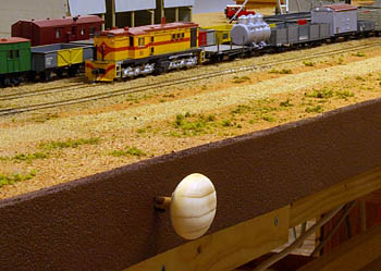
| Wooden cupboard knobs have been glued to the ends of many of the point actuation dowels. These improve the appearance, and are easier to operate than having to grip the end of the dowel. |
|
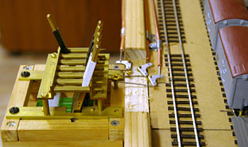
| The fiddle yard did not lend itself to convenient dowel operation of the points, so a Modratec lever frame has been installed. This actuates the points via Modratec wire-in-tube linkages. |
|
